30 October 2013

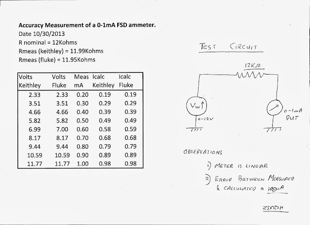
0 - 1mA Meter movement accuracy test

I have a 0-1mA meter in my junk box that I plan to use with a number of test instruments including the following:-

1) DC analog Voltmeter
2) An RF peak voltage detector
3) Various RF power meters

The results show good linearity of the meter. It also shows a difference of 10uA between the measured DC current and the calculated value. One would assume that the error is due to the omission of the meter resistance (ie. assumed = 0 ohms) in the calc value. Calculations show that there is  a 0.22volt drop across the meter.


20 October 2013

Field Trial and other fun at Manyane Pilanesberg NW province

We had tremendous fun this weekend as usual at Manyane campground in the Pilanesberg National Park. I took my homebrew rig (still on a piece of particle board) on it's first field trip. I deployed my EFHW up in a tree about 6 meters. This was not without incident. I managed to get the antenna well enough  over a tree that was a bit close to the operating position. I then tangled the launch rope in another tree in a vain attempt to get the end of the wire up higher. The result was I had to break the wire in order to get it down from the tree. The lesson learnt here is that the knot where the wire joins the rope needs to be smaller so that it can slide through branch forks easier.

I tried to make contact with om Daryl ZS6DLL in Centurion for his first CW QSO but unfortunately conditions were not good and Daryl also had some local QRM to deal with so no QSO was confirmed. I then checked into the AWA net at 2pm which was being run by John ZS6JBJ in Witbank. John gave me a 559 report. Dave ZS6AZP also checked in and gave me a 559 from Centurion area. I also copied Dave 559. John ZS5JON in the Durban area was unable to copy my 1.44watt signal although I could copy him about a 449. Conditions were definitely worse than usual for sure. It is also clear the 1.4 watts is not really enough power for net work.

I was able to enjoy a good QSO with om Monk about an hour before the AWA net and he gave me a 589 with the signal strength increasing. I also QSOd with om Mo ZS5BBW at about 5pm who gave me a 589. I concluded that band condx were unusual and that the band was very long. DX could clearly be heard.

On Sunday morning I was QRV in the rain, having had  a tremendous thunderstorm the night before and a dramatic drop in temperature.  By Sunday morning it was drizzling. I moved the rig onto the verandah with a resultant dog's leg in the antenna wire. I was unable to load the antenna properly. When I touched the rig there was a noticeable effect on the antenna performance. I was also unable to dim the SWR LED completely. I am not sure if this was due to a wet wire or the bent antenna wire. Nevertheless I could clearly hear the ZS0BOT beacon and also DX coming through from W Land.

My first field trial of the rig was a success. The rig performed according to expectation with the semi-break-in keying being a pleasure. I noticed some drift on warm up of the Rx and also some tweaking was needed as the temperature changes in the outdoor environment caused some small changes but entirely manageable.


Semi-Break-In Keying Control Circuits

After much experimentation and enduring very loud pops in my headphones on T/R switching of my homebrew field radio, I finally managed to develop workable semi-break-in keying control circuitry for this rig.  Albeit by deploying no less than 8 transistors to achieve the objective.

The Rx is basically as already described and is a W1FB NE602 based system with an audio preamp,  LM386 audio Amp and a high Q tuned audio filter between the Audio Pre-Amp and the Pre-Amp stage. This Rx generates tremendous headphone pops on any input disturbance. The Tx is a W7ZOI design and outputs 1.44Watts. This Tx was extremely simple to build and put on the air. The Tx is Xtal controlled to operate on 7020Khz and the Rx is VFO controlled with a very restricted tuning range from about 7017Khz to 7022Khz. A kind of RIT control.

Reference is made to the Control Circuit diagram below.

On KEY DOWN the following actions occur.

1) 12V is applied to the Sidetone Circuit.
2) The Pre-Amplifier is turned off
3) The input to the Audio Filter is muted.
4) The Transmitter Oscillator is keyed. The circuit includes a shaping function to reduce key clicks.
5) The T/R switch is switched to TX.

On KEY UP condition the Sidetone is stopped, the Pre-Amp is connected, and  the Tx oscillator is depowered. The T/R circuit will switch to the Rx after about 0.75 seconds and finally the Mute circuit will gracefully unmute the audio filter and audio amplifier amplifier after about 1 second. This has the effect of muting the pops associated with the change in state of all the other circuits BEFORE the audio recovers fully. Thus the pops are eliminated on Rx recovery. There is a slight thump on keydown but this is very much down in the noise and entirely tolerable from an operating perspective.

The tail delay of 1 second is about right although the first character of the transmitting station signal may be lost if the transmitting station is quick on the come back.

I am very pleased with the operation of the semi-break-in keying feature of this radio which makes it a pleasure to operate in the field.


17 October 2013

4:1 Broadband Transformer basic measurements

In the process of examining the possibility of deploying a broadband 4:1 transformer for matching a 50ohm filter to the final transistor in a PA system I performed some basic measurements as per the attached below.

In the actual implementation the transformer would transform the 50ohms load to 12.5ohms as seen by the collector. This would result in the theoretical  output of 5 watts QRP from a 12volt power supply.

Previous tests in terminating the 3dB attenuator pad in a 50ohm load showed that the attenuator is accurate and indeed has an insertion loss of 3dB. As can be seen in these results the power measured at P2 should therefore have been 360/2 = 180mW. In fact the measured result was 193mW. Indicating (I think) that in fact the input impedance to the transformer is something other than 50ohms. So the actual input impedance would be R=V^2/P = 3.11^2/180mW = 53.7 Ohms. ie 7% error. The load resistance was 200ohms as measured so the error must be in the transformer.

Looking further at the measured output power of 176mW it can be seen that there is a loss of 8.8% power in the transformer. Again the 200ohm load is accurate at least at DC level!

This teaches me that even the simplest measurements at RF will yield some very instructive results!

Using a return loss bridge (which I MUST build now) would yield the system performance with less maths!


16 October 2013

Experiments with an 80 meter Inverted L Quarter wave antenna

In trying to make contact across town with ZS6DLL om Daryl in Centurion at around midnight last night, I got to experiment with my 66ft end fed wire. Daryl was wanting to make his very first CW QSO. Well this was a goal worth trying to achieve asap. I didn't want him making the Big One with another station hi hi:)

I normally use this antenna for 40meters where it behaves as a half wave end-fed. For 40 meters of course it exhibits an end impedance of between 4000 and 5000 ohms. Thus a coupler is needed to perform an impedance match down to 50ohms. With a short 6ft counterpoise I have had great sucess with South Africa wide QSO's using 5 watts transmit power.

On 80meters this antenna has a theoretical end fed impedance of around 35-50ohms. Thus, providing a good ground can be established then it should be possible to connect the wire straight to the transmitter with perhaps some small adjustment using a traditional L type transmatch.

This wire is an inverted L with about 25feet hanging vertical and the rest horizontal. The wire is exactly 66ft long. So if I assume the popular dipole formula 468/F(Mhz) is correct then on 80 meters and applied also to a quarterwave then I would see resonance at F(Mhz) = (468/66)/2 = 3545Mhz.

I first started in the middle of the night by deploying 2 ground wires stretched along my garden lawn and right under the antenna. I suppose these wires were each about 40ft in length. Using my MFJ259B antenna analyzer I was able to obtain a dip at approx 3.8MHz with an SWR of 3.5:1.

If I now determine what my formula is I get C= F(Mhz)* Length (ft) = 3.8*66 = 251 which for a dipole would be 251*2= 501. Ie higher than the theoretical 468.

Since I wanted to operate on 3675Khz which is the local QRP hangout, I needed to add wire to the antenna. I added 6ft and was able to obtain a dip on frequency at 3579Khz with an SWR of 3.5:1. How does this compare with my locally derived formula?  F(Mhz) = 250/72 = 3472Khz. Thus the result does not agree with the theory... But it was the middle of the night and dark on the lawn!

I  then reoriented and lifted the antenna higher above the ground to 1bout 6ft for the section entering the radio. I also strung out a third much longer radial. This was approx 90ft long. This ground wire had the effect of dramatically reducing the SWR to 1.2:1 with little effect on the resonant frequency.

I was unable to QSO with ZS6DLL at around midnight. I could not hear any stations on the band which was a surprise, but then I never normally listen to 80m. The band was quiet. ZS6DLL may have some issues with his system (to be further checked out).

This morning at 6:30 I listened for the local QRP net on 3579Khz and heard nothing. I suspect the net was not operating. No station answered my CQ. I could hear weak stations on Phone further up the band. Noise was running higher at about S2. My Tx loaded up perfectly.

This set of rough experiments did indicate to me  that it may be possible to operate on 80 meters with my garden antenna. However more precise measurements need to be made to better understand what is happening. Clearly a longer set of ground wires and perhaps a few ground rods must make a significant difference. How do I do that and deploy wires without invoking the wrath of my XYL with the lawn mower!
15 October 2013

Dan Tayloe N7VE's SWR LED bridge from Hendricks QRP kits

I finally got around to assembling this kit after it lay in my 'Unbuilt Kit Box' for  a number of years. I built a small chassis for the unit with some scrap PC board. The unit was purchased from Hendricks QRP kits. I ran a few tests at different power levels and different reactive loads that were put in circuit with the use of a manual ATU.

Certainly the unit works as described and the LED is easily visible in the sun. The LED mostly extinguishes once a match of less than 1.1:1 is obtained. I look forward to using this during my next field trip.


07 October 2013

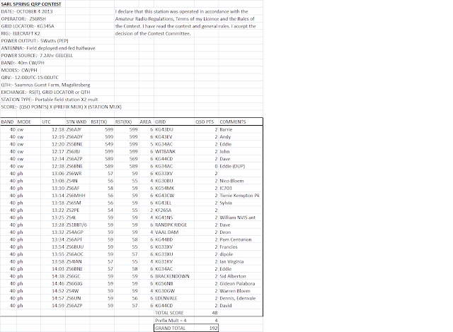
SARL QRP SPRING CONTEST 2013

I operated from our favorite dog walking QTH which is Saamrus in the Magaliesberg. I spent the first hour operating 40m CW but there were very few CW stations. I was given a few points by the ops on the AWA net which was appreciated for sure. Most of the activity was on Phone and I got the impression that the conditions were favorable. I was pleased with the performance of my modest setup. Herewith is my log submission along with a few pictures.


End-Fed Halfwave up about 9m at the top of the slope


02 October 2013

ZS6RSH Prototype Field Rig

Herewith some pics of the breadboard rig so far, and based on the W7ZOI Universal QRP rig with 1.5 watts output and Xtal controlled for 7020Khz.

The Rx is from W1FB's QRP notebook and using the ubiquitous NE602 mixer/oscillator. The oscillator is very stable and I now have a good RIT type tuning capability. Measurements to follow.

The control board has a sidetone multivibrator oscillator. The sidetone is routed through the very sharp active audio filter which improves the sidetone quality. Still room for improvement.

There is an active audio filter installed (specs to follow). This filter is tunable and works well in conjunction with the RIT type tuning control to optimize signal reception.

There is still much room for improvement. However the scope must be kept limited to the original objective which is a very simple rig that can be used for NVIS operations during daylight hours on short walks to the park over the weekend.

Room for improvement:

  1. Still a loud pop in my ear on T/R. Need to improve the changeover.
  2. Build a mini-boots to take it up to 5 watts
  3. Install a keyer chip
  4. Try a passive audio filter. Have a design from ZS4SF which has a nice 900Hz bandwidth. The one I am using is a bit sharp for this application under some band conditions.
  5. Install all in a rugged field box.
L-R. Audio Filter, DC Rx, Control/Sidetone, Tx-1.5W


01 October 2013

2N3553 Power Transistor Measurements

Looking at the Phillips data sheet for the 2N3553 transistor and then trying to compare the measurements I took for my 1.5Watt 40m transmitter based on W7ZOI design,  as follows:

Note: I am certainly not sure if the measurements are correct? Further analysis needed.

2N3553 is an NPN RF power transistor intended for VHF applications and recommended by W7ZOI as being suitable for the Universal QRP Transmitter (1.5Watts). He states that even under high SWR conditions the transistor will survive. I have not tested this (although I would love to) since I only have one of these transistors and they are quite expensive.

Case Type = TO-39. (I am running mine with no heatsink although it does get a little warm when sending normal type CW)


Vceo (Peak Collector Emitter voltage) = 40v max. My Vp-p on a 50 ohm load is 24volts (this as expected)
Icm (Peak Collector Current) = 1A. My Ic rms value is 213mA. Thus my Ic peak is 315mA. (not certain)
Ptot = 7W. This is max power dissipation. My tx has a calculated power dissipation of 1.5Watts. ie well below the rated max value and probably explains why it can run with high SWR? The spec also states an efficiency of 50%. I measured an efficiency of 53% which appears to be in the ballpark.

According to the spec. For f=175Mhz. Vce=28, Po = 2.5Watts and Gain = >10dB.

I measured as follows: f=7.020Mhz, Vce=24, Po=1.5Watts and Gain = 18dB. Seems reasonable??